|
| NICMOS Instrument Handbook for Cycle 11 | |||
|
|
Chopping and Dithering Patterns
There are a set of fifteen pre-designed patterns available for NICMOS observations. Users may define their own patterns as well, using the Pattern Parameters Form, during Phase II development. The pre-defined patterns include four dithering patterns, four chopping patterns, five dither-chop patterns, and two mapping patterns. For each of these, the observer will be able to specify the number of positions desired (2 to 40), the dither size (0 to 40 arcsec), the chop size (0 to 1440 arcsec, also used for mapping), and the orientation of the pattern with respect to either the detector or the sky. The
POS-TARGspecial requirement will still be available for offsetting the telescope and creating custom-design patterns as well, but there are a number of advantages to using the pre-designed patterns:
- They simplify the specification of complex observations in the Phase II proposal,
- All the observations pertaining to an exposure logsheet line in a pattern result in one association and are simultaneously calibrated and combined in the data calibration pipeline, including background calibration, cosmic ray removal, and flat fielding. Observations obtained with
POS-TARGdo not result in associations, and will have to be combined manually by the observer,- They permit the observation of a mosaic with a fixed position angle without fixing spacecraft roll, which increases the number of opportunities to schedule the observations.
Multiple exposures may be obtained at each position by the use of the number-of-iterations (NEXP) optional parameter. This may be useful for cosmic ray removal. In addition, exposures in different filters at each pattern position can be obtained by linking together exposure lines, such as "PATTERN 1 10-30" where exposure lines 20 and 30 specify different filters than the primary exposure line 10.
The fifteen NICMOS pre-designed patterns are listed in Table 11.1, together with applicable parameters, such as the allowed values for the number of steps in the pattern, the dither size, or the chop size. In addition, the figure number where the pattern is graphically shown is given in column 5 of Table 11.1. Offset sizes and number of steps in a pattern affect the amount of overhead time required to perform an observation (see Chapter 10). The effects of dithering or chopping on an astronomical image are shown in a set of examples in the next section.
Table 11.1: NICMOS Pre-designed Observing Patterns and Parameters NIC-SPIRAL-DITH2-40 NA 0-40 NA camera 11.3 NIC-SQUARE-WAVE-DITH2-40 NA 0-40 NA camera 11.3 NIC-XSTRIP-DITH2-40 NA 0-40 NA camera 11.3 NIC-YSTRIP-DITH2-40 NA 0-40 NA camera 11.3 NIC-ONE-CHOPNA 1-40 NA 0-1440 camera 11.4 NIC-TWO-CHOPNA 1-40 NA 0-1440 camera 11.4 NIC-SPIRAL-DITH-CHOPNA 1-40 0-40 0-1440 camera 11.5 NIC-XSTRIP-DITH-CHOPNA 1-40 0-40 0-1440 camera 11.5 NIC-YSTRIP-DITH-CHOPNA 1-40 0-40 0-1440 camera 11.5 NIC-ONE-SKY-CHOPNA 1-40 NA 0-1440 sky 11.6 NIC-TWO-SKY-CHOPNA 1-40 NA 0-1440 sky 11.6 NIC-XSTRIP-DITH-SKY-CHOPNA 1-40 0-40 0-1440 sky 11.6 NIC-SPIRAL-DITH-SKY-CHOPNA 1-40 0-40 0-1440 sky 11.6 NIC-MAP1-40 1-40 0-1440 0-1440 sky 11.6 NIC-SPIRAL-MAP2-40 NA 0-40 NA sky 11.6
Note on Orientation:
The new pattern parameter syntax requires additional input on orientation. Specifically, the pattern must be defined in either the
POS-TARG(camera) frame or theCELESTIAL(sky) frame. An orientation angle may be specified as well (the usual default is 0°). In thePOS-TARGframe, this is the angle of the motion of the target from the first point of the pattern to the second, counterclockwise from the x detector axis (the directions are defined in Figure 6.1). In theCELESTIALframe, the angle is measured from North through East.Note that some of the pattern names in Table 11.1 are doubled except for an additional -SKY-. These can be specified either as
POS-TARGorCELESTIALdefault (see below for details).Move the sky or the telescope?
The new pattern syntax attempts to resolve the confusing dichotomy in the old pattern implementation, as to whether the pattern moves the telescope or the target. It does this by providing the two reference frames described above. Patterns done in the
POS-TARGreference frame will move the target, just as the "POS-TARG" special requirement does. Patterns done in theCELESTIALreference frame will move the telescope, as was done with the original implementation of the NICMOS patterns. The target will move in the opposite direction on the image, in theCELESTIALframe relative to thePOS-TARGframe.Dither Patterns
The dither patterns are recommended for the background subtraction from observations of point sources (longward of 1.7 microns), and for the reduction of sensitivity variations and bad pixel effects. The four types of canned dither routines are
NIC-SPIRAL-DITH, NIC-SQUARE-WAVE-DITH,NIC-XSTRIP-DITH, andNIC-YSTRIP-DITH. Most of the names are self-explanatory: the NIC-SPIRAL-DITHpattern produces a spiral around the first pointing; the NIC-SQUARE-WAVE-DITHpattern covers extended regions by moving along a square-wave shape; the NIC-XSTRIP-DITHand NIC-YSTRIP-DITHpatterns move the target along the x and y directions of the detector, respectively. The difference between the NIC-XSTRIP-DITH and the NIC-YSTRIP-DITHpatterns is that the first moves by default along the grism dispersion (more or less), while the second moves orthogonal to the grism dispersion axis. These patterns are illustrated in Figure 11.3Note that there is an additional parameter for dithering patterns, to center the pattern on the target. The default is to start the dithering at the target position.
Figure 11.3: Dither Patterns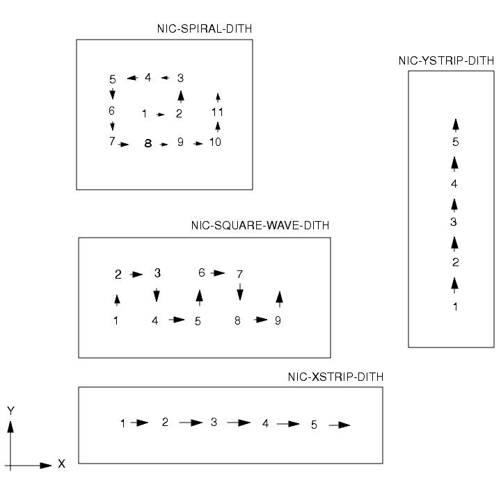
Chop Patterns
The chop patterns are recommended for measuring the background adjacent to extended targets. For each chop pattern, half of the exposures are taken on the target (position 1). There are two basic patterns,
NIC-ONE-CHOPandNIC-TWO-CHOP. The NIC-ONE-CHOPpattern produces one image of the target and one image of the background. The NIC-TWO-CHOPpattern produces one image (with two exposures) of the target and two background images, with the background fields positioned on opposite sides of the target. These patterns may be repeated if necessary: note that rather than specifying the number of points in the pattern, the observer specifies the number of repeats of the pattern. For example, calling theNIC-TWO-CHOPpattern with number of patterns of 1 will produce four images, one on the target, one off to one side (default -x detector direction, see next para.), one back on the target, and one off to the other side. If the number of patterns is set to 2, the observer will get eight images, and so forth. Chop patterns are illustrated in Figure 11.4.Because chopping is best done to empty regions of the sky, we provide a set of chopping patterns that are in the
Figure 11.4: Chop PatternsCELESTIALcoordinate system, as well as the standard set (that are in thePOS-TARGframe). These have the wordSKYin their name, and must have an orientation angle (degrees E from N for the first motion of the pattern) supplied. These should be used when the region around the target contains some objects that should be avoided when measuring the background.SKYpatterns are illustrated in Figure 11.6.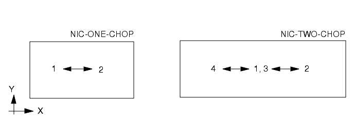
Combined Patterns
The combined patterns permit dithering interleaved with chops to measure the background. They are recommended for simultaneous minimization of detector artifacts and background subtraction, for observations beyond 1.7 microns. Three types of combined patterns are implemented:
NIC-SPIRAL-DITH-CHOP, NIC-XSTRIP-DITH-CHOP,andNIC-YSTRIP-DITH-CHOP. Their characteristics are analogous to the dither patterns NIC-SPIRAL-DITH, NIC-XSTRIP-DITH, and NIC-YSTRIP-DITH, respectively, with the addition that each dither step is coupled with a background image obtained by chopping. These combined patterns are shown in Figure 11.5.In a manner similar to the regular chopping patterns, the combined patterns have "SKY" versions implemented in the
Figure 11.5: Combined PatternsCELESTIALframe. Since these require an orientation angle, there is no NIC-YSTRIP-DITH-SKY-CHOP, however: this is redundant with NIC-XSTRIP-DITH-SKY-CHOP. These are illustrated in Figure 11.6.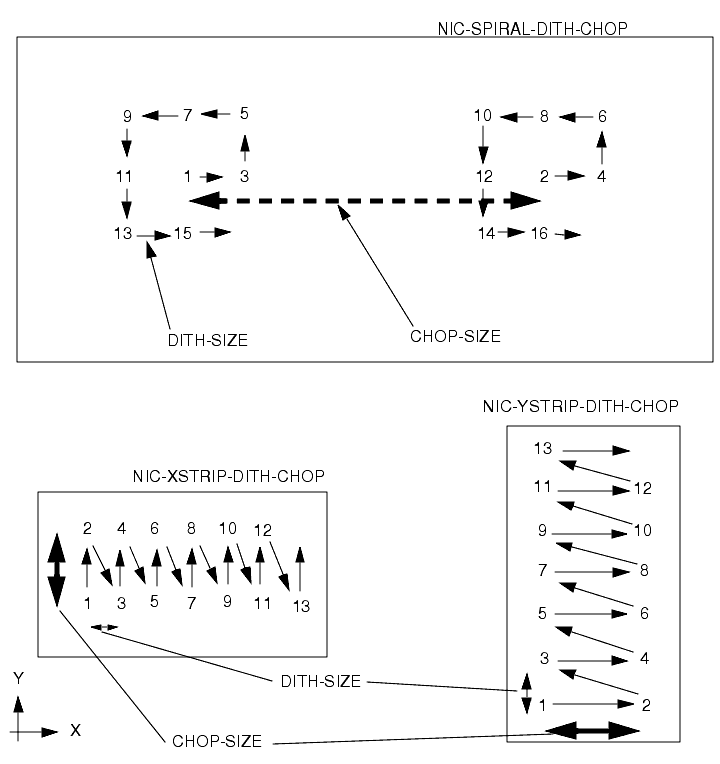
Map Patterns
A new addition to the suite of "canned" patterns are the two
MAPsequences. These allow the telescope to be pointed at a regular grid of points, doing a series of exposures at each point. These are done in theCELESTIALframe, so an orientation angle must be supplied, and the telescope motion on the sky is specified (rather than the target motion relative to the detector, see note above). TheNIC-SPIRAL-MAPsequence is basically the NIC-SPIRAL-DITHsequence in theCELESTIALframe, and automatically maps the (square or rectangular) region around the target. The NIC-MAP sequence defines an arbitrary parallelogram on the sky. The observer may specify the number of points in each of two directions, and the position angle (E of N) of each direction.As with the dithering patterns, the observer has the option of specifying whether the target is centered in the pattern or not. The target will be centered in the NIC-SPIRAL-MAP pattern if there are 9, 25, 49,... points in the pattern, but will not necessarily be centered otherwise. The observer can specify if the target should be centered along one axis or the other, or both, of the parallelogram defined by the sequence. These are illustrated in Figure 11.6.
Figure 11.6: Patterns on the sky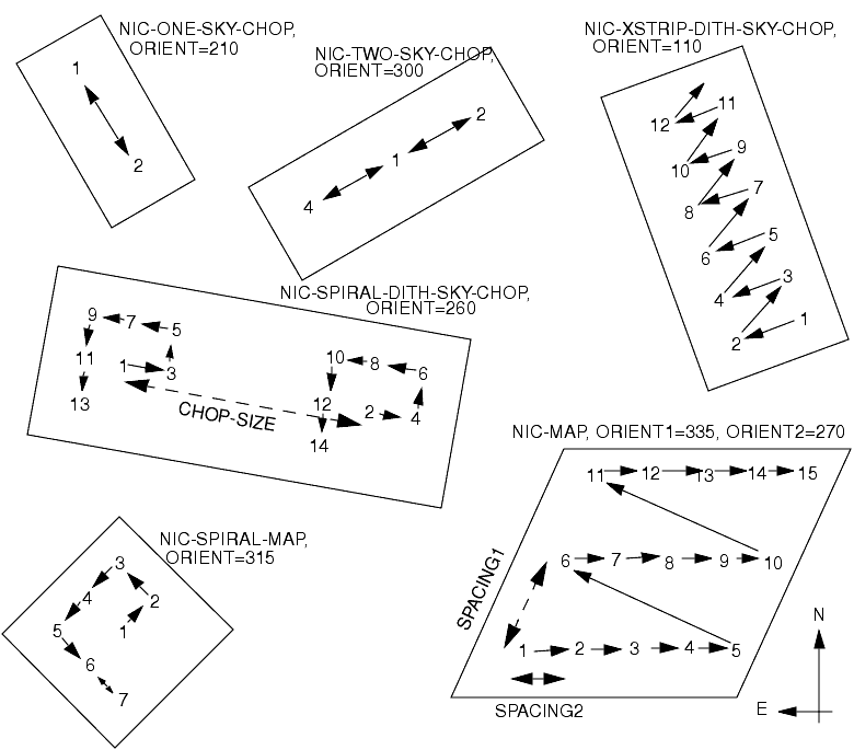
|
Space Telescope Science Institute http://www.stsci.edu Voice: (410) 338-1082 help@stsci.edu |