


Detailed Instrument Description
Internal Calibration System
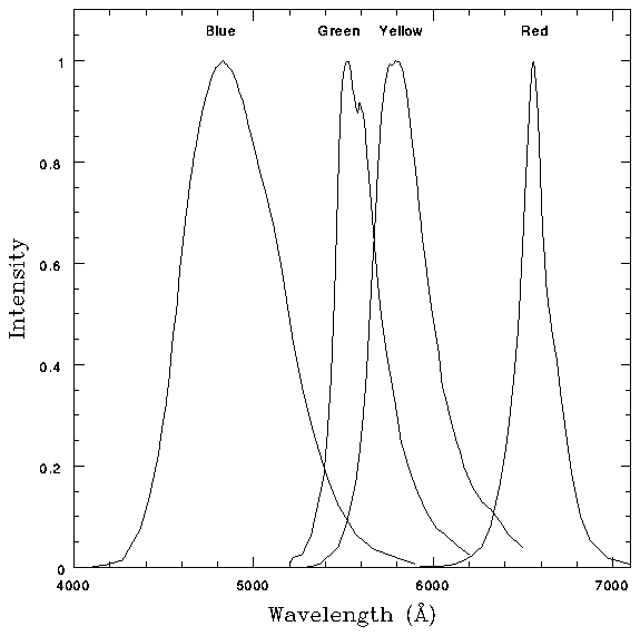
When the shutter is closed, an Al + MgF2 mirror (see Figure 4.2) reflects the light beam from a light emitting diode (LED) calibration source into the optical path of the relay. The position of the source and the curvature of the mirror insure a quasi flat field illumination of the object plane. The unit consists of seven LEDs (two red, two yellow, two green and one blue) illuminating an integrating sphere. Their normalized emission spectra are shown in Figure 4.6. The unit is capable of illuminating both calibration mirrors simultaneously. Each LED output can be set to 256 separately commandable intensity levels. The calibration system will be used to determine the detector's intensity transfer function, the uniformity of response, the FOC response to visible light and the geometric distortion. A ground-based comparison between external and LED flat field illumination of the detectors at the same wavelengths shows that the spatial variations of LED illumination are less than xb1 3% peak to peak over most of the field of view. The only exception is due to one edge of the circular mirror on the back of the shutter for the F/48 relay preventing LED light from illuminating the upper left hand corner of the F/48 frame. The calibration unit does not experience the same vignetting of an external source. This must be taken into account when comparing internal and external flat fields. As mentioned previously, the F/96 detector is not expected to have any vignetting, nor is there any evidence of it. UV flat fields have been obtained using observations of the inner region of the Orion Nebula.
Figure 4.6: Normalized Emission Spectra of the Calibration LEDs.
- Figure 4.6: - Normalized Emission Spectra of the Calibration LEDs.
-
Generated with CERN WebMaker