


At the locations of the FOC entrance apertures, the OTA focal plane makes an angle of 10.05xfb with the normal to the ST axis. This plane is the object plane for the FOC optical relays. The COSTAR-corrected focal plane is inclined to this plane, which induces a field-dependent focus variation that is described more fully in "Image quality and Field Dependence of the PSF" on page 65. The axes of symmetry of the two FOC cameras D96 and D48 that run through the center of the apertures, perpendicular to and intersecting on the V1 axis form an angle of 30xfb . The D96 axis forms an angle of 30xfb with the +V2 axis and D48 an angle of 30xfb with the +V3 axis.
Figure 4.3: Location of the FOC Entrance Apertures on the HST Focal Plane Projected onto the Plane of the Sky. In this perspective V1 is directed into the paper at the center of the WFPC2 pattern. V1, V2 and V3 form the HST right handed coordinate system defined in the Call for Proposals.
An expanded view of the two apertures in exactly the same perspective is shown in Figures 4.4 and 4.5. The camera aperture for the F/96 relay is a circular diaphragm of 10.5 millimeters in diameter corresponding to 24 arcseconds on the sky in the COSTAR-corrected field, centered at point O with two 2 millimeter-long protruding opaque metal fingers oriented @ 30xfb to the D96 line and parallel to the V2 axis. The finger on the right is 0.112 millimeters thick (0.25 arcsecond in the sky) while the other is 0.223 millimeters thick (0.5 arcsecond in the sky). The directions of increasing sample (S) and line (L) numbers for the extended SDS format define the image coordinate system with its center at point C96. This system is aligned with the X, Y reference system used to designate the orientation of the apertures on the sky in the Proposal Instructions. The corners ABCD of the 512 1024 zoomed format are marked on Figure 4.4. The large 14 14 arcsecond square marks the limit of the extended format. The opaque coronographic fingers are indicated by the hatched regions. The V1 axis is 4.658 arcminutes from O in the direction indicated to V1. The fully corrected field point for the F/96 relay coincides with C96. Due to the presence of a reseau mark at C96, the reference position for F/96 images has been moved off the center to R96, located at (S,L) = (556,536) and shown in Figure 4.4.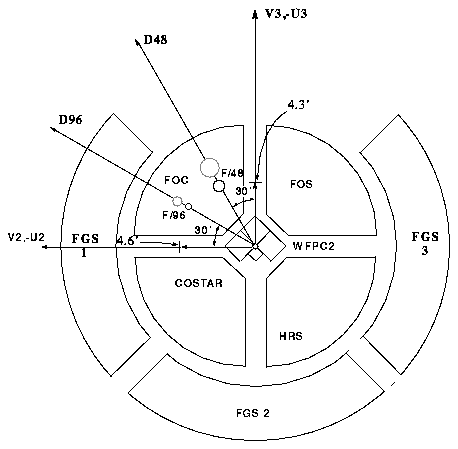
Figure 4.4: Camera Entrance Aperture for the F/96 Relay Projected Onto the Sky.
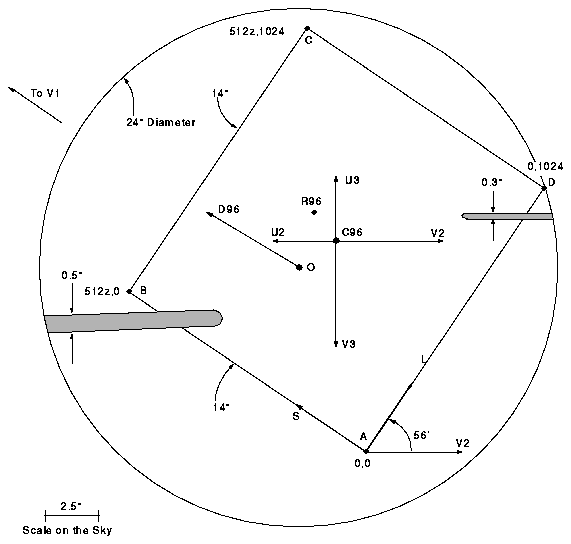
Figure 4.5: Camera Entrance Aperture for the F/48 Relay Projected Onto the Sky. KI along the spectrograph slit coincides with the reference axis x that is used to designate the orientation of the apertures on the sky in the Proposal Instructions. The point P is the optimally corrected field point for the F/48 relay and the new 512 512 imaging format is shown outlined with a bold line.
The F/48 entrance aperture is shown in Figure 4.5. The center O of the main aperture coincides with the center of the extended SDS format and lies on the sagittal focus while the center J of the slit lies on the tangential focus of the OTA.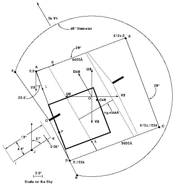
Because of vignetting induced in the FOC by moving the OTA exit pupil from 7 meters to 530 millimeters from the F/48 entrance aperture, it is not possible to have the center of the extended field unvignetted as well as all of the slit. The best compromise, which maintains the utility of the long slit as well as providing an imaging field useful for spectrograph acquisitions, was to move the optimally corrected field point from the center of the extended format to the point P, which is where the hypothetical extension of the slit would meet the edge of the extended imaging format. The default 512 512 imaging format has therefore been moved to that corner of the extended format, and has been outlined in Figure . In this way, over half of the slit suffers less than 20% vignetting while the newly moved 512 512 imaging format is unvignetted over more than 80% of its area. Full vignetting contours are shown in "Uniformity of Response (Flat Fielding)" on page 80.
The main aperture is essentially a circular diaphragm with a diameter of 21 millimeters corresponding to 48 arcseconds on the sky in the COSTAR-corrected field, except for an oblique truncation at points E and H. A thin, 0.15 arcsec wide opaque finger points to O from point G. A 5.689 millimeters (12.8 arcsecond) long, 0.028 millimeters (0.064 arcsecond) wide slit centered at J is located between points I and K. This slit forms the defining aperture of the spectrograph for the F/48 relay. The corners of the 512z 1024, 28 28 arcsecond squared extended imaging format are given on Figure as points A, B, C and D. When the spectrograph mirror is in place, the aperture is imaged onto the extended SDS format as shown in Figure with the dashed lines representing the inner and outer edge of the spectrally dispersed image of the slit and the edge of the main aperture drawn for the specific case of the Hg line at 4358Å. The opaque finger (originally used for target acquisition) is indicated by the dark region. V1 is 4.312 arcminutes from P in the direction indicated to V1. A part of the dispersed main aperture falls in the right hand quarter of the extended format and may be eliminated by tailoring the observing format to the region inside the slit area. Wavelength increases in the direction indicated by l from 3600Å to 5400Å in first order.
In order to predict with reasonable accuracy the location and orientation of an extended source in the FOC fields of view and to determine whether or when the required instrument orientations are compatible with the HST roll angle restrictions, it may be useful to locate with respect to the S, L axes on Figures 4.4 and 4.5 the celestial reference axes for that particular target and viewing configuration. To accomplish this, simply follow the procedures described in the Call for Proposals.
To specify a particular orientation of the apertures with the ORIENT special requirement of the exposure logsheets (see Proposal Instructions for a more detailed description), place the object to be observed in the proper configuration on the entrance aperture shown in Figures 4.4 and 4.5. This will determine the desired positions of the N and E directions on the same apertures. The angle between these directions and the U3 axis drawn on these figures (measured E from N) is the angle to specify in this special requirement.
The aperture configurations described in this section for the F/96 correspond to the position determined during the first in-flight tests of the FOC + COSTAR system and the Cycle 5 alignment calibrations. Additional similar calibrations will be performed in Cycle 5 and 6 to monitor the stability of these positions and to ensure that the FOC apertures alignment is maintained at better than 0.2''. No in-flight calibration has been performed for the F/48 yet, although the only astronomical target imaged so far has been acquired with an accuracy of ~ 2''. Actual images of the extended 512z 1024 pixels squared pre-COSTAR F/48, pre-COSTAR F/96, and pre-COSTAR F/48 spectrograph fields obtained in orbit with external flat field illumination of the FOC entrance apertures are shown in Figures 12.1 through 12.3 in Chapter 12. The extended format 512z 1024 pixel images have been dezoomed and displayed in a 1024 1024 pixel format. The occulting fingers, spectrograph slit, reseau marks appear clearly together with some blemishes and large scale response inhomogeneities. The latter are discussed in more detail in "Uniformity of Response (Flat Fielding)" on page 80 and "Geometric Distortion and Stability" on page 87.
Generated with CERN WebMaker