Introduction
Built at the Jet Propulsion Laboratory by an Investigation Definition Team (IDT) headed by John Trauger, WFPC2 was the replacement for the first Wide Field and Planetary Camera (WF/PC-1) and includes built-in corrections for the spherical aberration of the HST Optical Telescope Assembly (OTA). The WFPC2 was installed in HST during the First Servicing Mission in December 1993.
Early IDT report of the WFPC2 on-orbit performance: Trauger et al. (1994, ApJ, 435, L3)
A more detailed assessment of its capabilities: Holtzman et al. (1995, PASP, 107, page 156 and page 1065).
The WFPC2 was used to obtain high resolution images of astronomical objects over a relatively wide field of view and a broad range of wavelengths (1150 to 11,000 Å). WFPC2 was installed during the first HST Servicing Mission in 1993 and removed during Servicing Mission 4 in 2009. WFPC2 data can be found on the MAST Archive.
Announcements
March 2021
A new geometric distortion reference file based on Gaia DR3 is now available in the Analysis section.
ISRs
Filter Results
-
December 14, 2010P. L. Lim, M. Quijada, S. Baggett, J. Biretta, J. MacKenty, R. Boucarut, S. Rice, and J. del Hoyo
-
2010-04: The Dependence of WFPC2 Charge Transfer Efficiency on Background Illumination
December 01, 2010D. Golimowski and J. Biretta -
2010-03: WFPC2 CTE for Extended Sources: I. Photometric Correction
August 13, 2010N. A. Grogin, R. Lucas, D. Golimowski, and J. Biretta
Accordion
-
Optical Configuration
While it was in operation, the WFPC2 field of view was located at the center of the HST focal plane. The central portion of the f/24 beam coming from the OTA would be intercepted by a steerable pick-off mirror attached to the WFPC2 and diverted through an open port entry into the instrument. The beam would then pass through a shutter and interposable filters. An assembly of 12 filter wheels contained a total of 48 spectral elements and polarizers. The light would then fall onto a shallow-angle, four-faceted pyramid, located at the aberrated OTA focus. Each face of the pyramid was a concave spherical surface, dividing the OTA image of the sky into four parts. After leaving the pyramid, each quarter of the full field of view would then be relayed by an optically flat mirror to a Cassegrain relay that would form a second field image on a charge-coupled device (CCD) of 800 x 800 pixels. Each of these four detectors were housed in a cell sealed by a MgF2 window, which is figured to serve as a field flattener.

The aberrated HST wavefront was corrected by introducing an equal but opposite error in each of the four Cassegrain relays. An image of the HST primary mirror would then be formed on the secondary mirrors in the Cassegrain relays. The spherical aberration from the telescope's primary mirror would be corrected on these secondary mirrors, which were extremely aspheric; the resulting point spread function was quite close to that originally expected for WF/PC-1.
Field of View

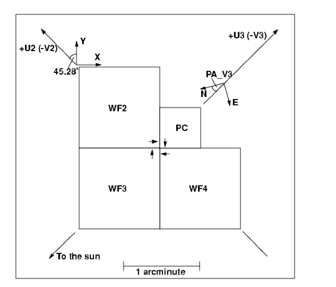
The U2,U3 axes were defined by the "nominal" Optical Telescope Assembly (OTA) axis, which was near the center of the WFPC2 FOV. The readout direction was marked with an arrow near the start of the first row in each CCD; note that it rotated 90 degrees between successive chips. The x,y arrows mark the coordinate axes for any POS TARG commands that may have been specified in the proposal. An optional special requirement in HST observing proposals, places the target an offset of POS TARG (in arcsec) from the specified aperture.
Camera Configurations Camera Pixels Field of View Scale f/ratio PC (PC1) 800 x 800 36" x 36" 0.0455" per pixel 28.3 WF2, 3, 4 800 x 800 80" x 80" 0.0996" per pixel 12.9
-
A Note about HST File Formats
Data from WFPC2 are made available to observers as files in Multi-Extension FITS (MEF) format, which is directly readable by most PyRAF/IRAF/STSDAS tasks. All WFPC2 data are now available in either waivered FITS or MEF formats. The user may specify either format when retrieving that data from the HDA. WFPC2 data, in either Generic Edited Information Set (GEIS) or MEF formats, can be fully processed with STSDAS tasks.
The figure below provides a physical representation of the typical data format.

Resources
- The WFPC2 Data Analysis Tutorial provides cookbook examples of converting and working with WFPC2 images.
- More information on WFPC2 data can be found in Chapter 2.1 of the WFPC2 Data Handbook.
-
Charge Traps
There are about 30 pixels in WFPC2 that are "charge traps" which do not transfer charge efficiently during readout, producing artifacts that are often quite noticeable. Typically, charge is delayed into successive pixels, producing a streak above the defective pixel. In the worst cases, the entire column above the pixel can be rendered useless. On blank sky, these traps will tend to produce a dark streak. However, when a bright object or cosmic ray is read through them, a bright streak will be produced. Here, we show streaks (a) in the background sky, and (b) stellar images produced by charge traps in the WFPC2. Individual traps have been cataloged and their identifying numbers are shown.

Warm Pixels and Annealing
Decontaminations (anneals), during which the instrument is warmed up to about 22o C for a period of six hours, were performed about once per month. These procedures are required in order to remove the UV-blocking contaminants which gradually build-up on the CCD windows (thereby restoring the UV throughput) as well as fix warm pixels. Examples of warm pixels are presented in the figure below.

-
Calibration Procedure Estimated Accuracy Notes Bias subtraction 0.1 DN rms Unless bias jump is present Dark subtraction 0.1 DN/hr rms Error larger for warm pixels; absolute error uncertain because of dark glow Flat fielding <1% rms large scale Visible, near UV 0.3% rms small scale Visible, near UV ~10% F160BW; however, significant noise reduction achieved with use of correction flats Relative Photometry Procedure Estimated Accuracy Notes Residuals in CTE correction < 3% for the majority (~90%) of cases up to 1-% for extreme cases (e.g., very low backgrounds) Long vs. short anomaly (uncorrected) < 5% Magnitude errors <1% for well-exposed stars but may be larger for fainter stars. Some studies have failed to confirm the effect. (see Chapter 5 of IHB for more details) Aperture correction 4% rms focus dependence (1 pixel aperture) Can (should) be determined from data <1% focus dependence (> 5 pixel) Can (should) be determined from data 1-2% field dependence (1 pixel aperture) Can (should) be determined from data Contamination correction 3% rms max (28 days after decon) (F160BW) 1% rms max (28 days after decon) (filters bluer than F555W) Background determination 0.1 DN/pixel (background > 10 DN/pixel) May be difficult to exceed, regardless of image S/N Pixel centering < 1% Absolute Photometry Precedure Estimated Accuracy Sensitivity < 2% rms for standard photometric filters 2% rms for broad and intermediate filters in visible < 5% rms for narrow-band filters in visible 2-8% rms for UV filters Astrometry Procedure Estimated Accuracy Notes Relative 0.005" rms (after geometric and 34th-row corrections) Same chip 0.1" (estimated) Across chips Absolute 1" rms (estimated) -
Photometric Systems Used for WFPC2 Data
The WFPC2 flight system is defined so that stars of color zero in the Johnson-Cousins UBVRI system have color zero between any pair of WFPC2 filters and have the same magnitude in V and F555W. This system was established by Holtzman et al. (1995b)
The zeropoints in the WFPC2 synthetic system, as defined in Holtzman et al. (1995b), are determined so that the magnitude of Vega, when observed through the appropriate WFPC2 filter, would be identical to the magnitude Vega has in the closest equivalent filter in the Johnson-Cousins system.
\(m_{AB} = -48.60-2.5\log f_\nu \)
\(m_{ST} = -21.10-2.5\log f_\lambda\)
Photometric Corrections
A number of corrections must be made to WFPC2 data to obtain the best possible photometry. Some of these, such as the corrections for UV throughput variability, are time dependent, and others, such as the correction for the geometric distortion of WFPC2 optics, are position dependent. Finally, some general corrections, such as the aperture correction, are needed as part of the analysis process. Here we provide examples of factors affecting photometric corrections.
-
Cool Down on April 23, 1994
-
PSF Variations
-
34th Row Defect
-
Gain Variation
-
Pixel Centering
-
Possible Variation in Methane Quad Filter Transmission
Polarimetry
WFPC2 has a polarizer filter which can be used for wide-field polarimetric imaging from about 200 through 700 nm. This filter is a quad, meaning that it consists of four panes, each with the polarization angle oriented in a different direction, in steps of 45o. The panes are aligned with the edges of the pyramid, thus each pane corresponds to a chip. However, because the filters are at some distance from the focal plane, there is significant vignetting and cross-talk at the edges of each chip. The area free from vignetting and cross-talk is about 60" square in each WF chip, and 15" square in the PC. It is also possible to use the polarizer in a partially rotated.

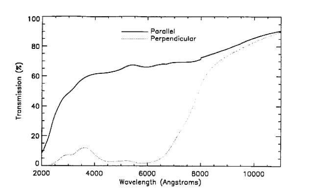
Accurate calibration of WFPC2 polarimetric data is rather complex, due to the design of both the polarizer filter and the instrument itself. WFPC2 has an aluminized pick-off mirror with a 47° angle of incidence, which rotates the polarization angle of the incoming light, as well as introducing a spurious polarization of up to 5%. Thus, both the HST roll angle and the polarization angle must be taken into account. In addition, the polarizer coating on the filter has significant transmission of the perpendicular component, with a strong wavelength dependence.
Astrometry
Astrometry with WFPC2 means primarily relative astrometry. The high angular resolution and sensitivity of WFPC2 makes it possible, in principle, to measure precise positions of faint features with respect to other reference points in the WFPC2 field of view. On the other hand, the absolute astrometry that can be obtained from WFPC2 images is limited by the positions of the guide stars, usually known to about 0.5" rms in each coordinate, and by the transformation between the FGS and the WFPC2, which introduces errors of order of 0.1"
Because WFPC2 consists of four physically separate detectors, it is necessary to define a coordinate system that includes all four detectors. For convenience, sky coordinates (right ascension and declination) are often used; in this case, they must be computed and carried to a precision of a few mas, in order to maintain the precision with which the relative positions and scales of the WFPC2 detectors are known. It is important to remember that the coordinates are not known with this accuracy. The absolute accuracy of the positions obtained from WFPC2 images is typically 0.5" rms in each coordinate and is limited primarily by the accuracy of the guide star positions.
2021 Updated Geometric Distortion Correction w.r.t Gaia EDR3.
As of March 2021 we recommend the use of new for geometric distortion calibration based on Gaia EDR3. The full description of the astrometric calibration is provided in "A comprehensive astrometric calibration of the HST WFPC2: distortion mapping" Casetti-Dinescu, D.I., Girard, T.M., Kozhurina-Platais, V., Platais, I., Anderson, J. (2021), submitted to PASP Mar 2021 (publication pending, AAS bulletin here).
The application of the improved calibration geometric distortion is provided here.
Please refer to the README file for instructions on use.
Please note that these files are different from the ones provided via the Calibration Reference Data System (CRDS).
-
Pre-footer
HST Help Desk
Please contact the HST Help Desk with any questions.

